The S0 truss
is included as part of ISS combo kit #1 from AXM. The parts occupy a total of six pages (four pages for the truss, one page for the MT, two pages for the MBS). AXM has provided excellent build instructions for this component. The instruction manual for the truss and MT is a whopping 52 pages! Instructions for construction of the MBS (24 pages) can be found here.
I started my build of this component in the summer of 2017 during my work on the
Destiny module. I quickly realized that, in order to correctly implement magnetic attachment of the S0 truss to Destiny, I would need to build the outer shell, MT-SAS, and strut assemblies for S0 and align their magnetic connectors with those placed on Destiny.
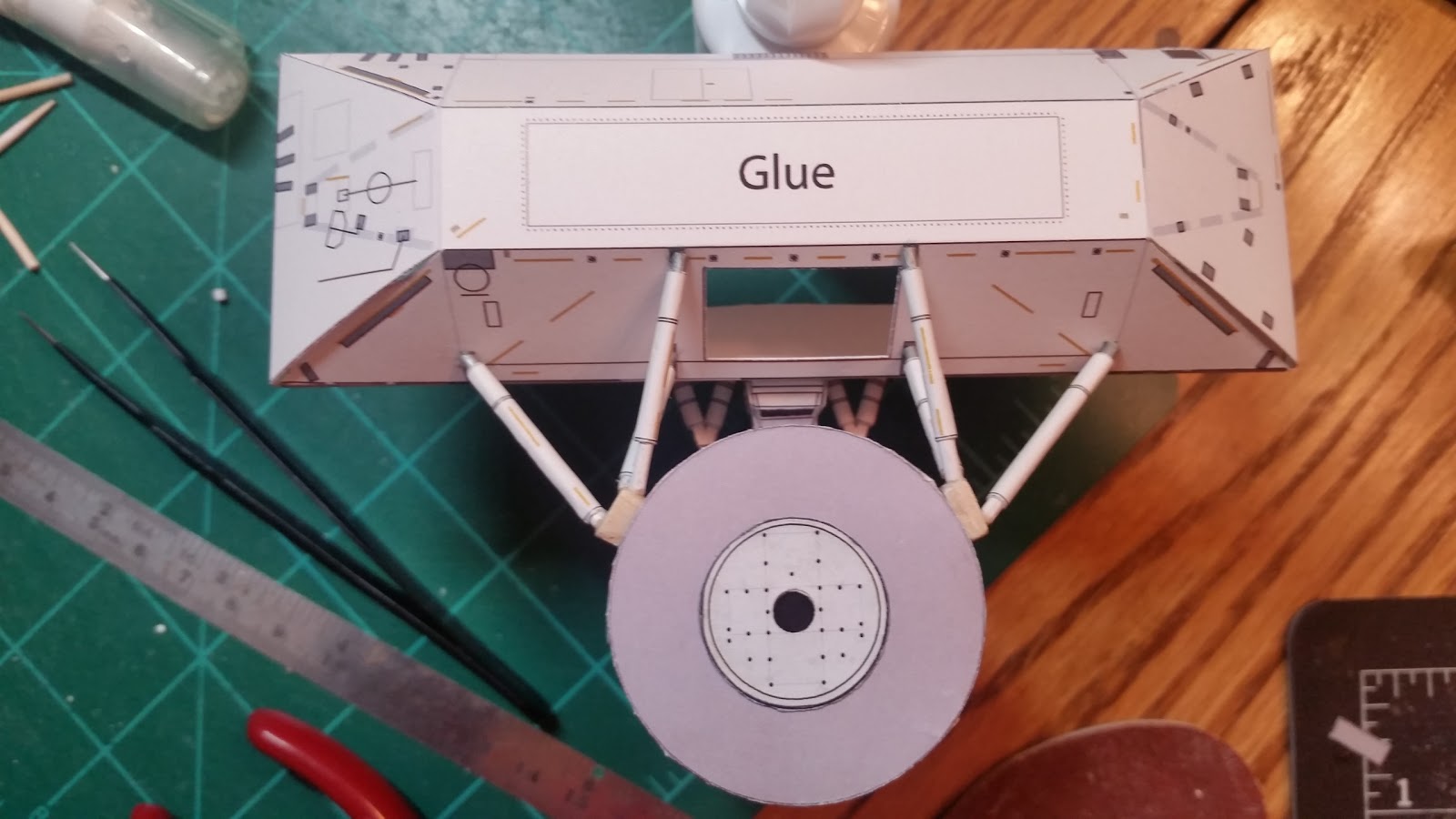
I started by cutting out the main S0 truss shell.
Next, I extruded the parts that make up the forward and aft struts.
I then fabricated the MT-SAS and placed 2 magnets on the zenith side of the base plate, making sure to align their polarity with those already placed within the Destiny keel pin fixture and LCA components.
I lapped the truss shell joiner tabs and used adhesive tape to temporarily join the tabs to form the outer shell. I affixed the MT-SAS to the proper location on the lower forward side of the truss shell.
Next, I focused on assembly and angled orientation of the forward struts. S
mall metal plates were affixed to the foot of each strut so that they will magnetically attach to the mount points on the Destiny hull. I embellished the strut arms with metal wire representing hand holds.
I then placed the LCA over the keel pin and connected the S0 truss shell to Destiny using the MT-SAS magnetic connection to the LCA. I glued the upper end of each forward strut to the proper locations on the truss nadir forward section to achieve proper strut alignment.
Next, I turned my attention to the aft struts.
I determined that a central mount point was necessary for each aft strut assembly in order to accommodate magnetic attachment to Destiny's hull. I cut out two small blocks of balsa and affixed a piece of metal plate to the bottom of each block to accommodate magnetic attachment. I then drilled recess holes at proper angles on each block and then glued the individual struts to the block at these locations. Zenith ends of each strut arm were then glued to the designated mount points on the S0 truss shell.
At this point I had assembled enough of the S0 truss to ensure proper mating to the Destiny module. I set aside the S0 shell and worked to complete the Destiny build and other components that arrived at the station ahead of S0 (Leonardo MPLM, Rafaello MPLM, Quest Airlock, Pirs).
I picked back up with assembly of the S0 truss in late March of 2018.
I first fabricated the aft tray door. I extruded the front and back sides of the tray and performed layering and embellishment the ammonia coolant lines and connector boots to increase depth and realism in this area, commonly referred to as the "rat's nest". I chose to not attach the Node 1 swing arm until the tray is mated to the S0 in order to avoid possible damage.
I removed the tape used to temporarily join the shell together in support of the Destiny build.
I then set to work on extruding the inner truss face.
Next, I began the task of extruding the interior wall faces. I warmed up with the inner end cap walls. I cut out two sets in order to add depth to the inner wall beams, layering the beam-only cutouts atop a second set that don't have the white background areas cut out.
I then moved onto the interior walls. There are four parts for each wall (two outer faces, two spacers for thickness/rigidity).
Did I mention that Yuri Gagarin made a surprise inspection visit just before his birthday to check on my progress?
I printed out a second copy of the inner truss face parts page to add depth for the remaining inner wall beam area. I cut out the white areas of the face, paying close attention to preserving cable strands that overlap the edges of the beams.
I then proceeded to cut out and assemble the inner wall platforms and various MDMs, utility rail control units, trailing umbilical system cable reels, and video switches that sit atop them.
Next, I cut out and assembled the four DC-to-DC Conversion Units (DDCU). I layered the end caps to increase realism.
All interior parts are now ready for placement on the inner truss face.
Next, I affixed the inner truss face beams cutout to the full inner truss face piece.
I then joined the inner face laps.
Small sections of 32-gauge coated white wire were placed at the middle of the inner side of the hinge point for the aft cable tray.
I then proceeded to affix the inner wall platforms a the prescribed locations.
I moved onto cutting out and building the 4 main bus switching units (MBSU), spare DDCU, and Extravehicular Charged Particle Directional Spectrometer (EV-CPDS).
I then focused on removable placement of the stowed Node 2 umbilicals. I previously buil these umbilicals in their deployed configuration during the Destiny build. I now needed to modify them for a stowed configuration with stowage end caps.
First, I bent sections of rigid wire to follow the bend angle for each umbilical. I then segmented both umbilicals at the bend and used a piece of rigid wire bent in a narrow "U" shape to connect the parts in a stowed configuration. the storage end cap was then affixed to each umbilical using removable sticky pads.
The backside of each umbilical is already fitted for magnetic attachment. I measured and pinpointed spots for both mount points on the truss face (upper starboard side forward and starboard aft panels, close to zenith) and then affixed small pieces of magnets at prescribed points to grab each umbilical.
I moved onto completion of the inner end cap walls.
As with many components in my ISS build, the S0 truss attaches to the ends of the S1 and P1 truss segments magnetically. Implementing a magnetic attachment requires exact placement of magnets on both sides to ensure a flush fit. I printed out copies of the inner wall parts pages for the S1 and P1 trusses and extruded the end cap wall parts. As with the S0 end walls, I also layered these end caps to gain depth on the beams. I labeled each part on the backside with a pencil to ensure that the correct part is used for the connections. Next, I carefully placed magnets at the outer angle points of the beams of the S0 parts, making sure that the polarity for all magnets was identical.
I then aligned corresponding end cap parts from the S1 and PI back-to-back with their S0 counterparts and glued the magnets, adjusting where necessary to ensure a flush fit.
Some magnets may be visible when closely inspecting the inner portion of the truss segments. I decided to cover the magnets with selected sections of the truss beams to disguise the magnets as best a possible.
Next, I proceeded to mate the inner shell and walls structure to the outer shell. I glued the inner walls and end caps to the edges of the inner shell and then glued the upper and lower forward faces the the front of the inner wall edges.
I then affixed the aft cable tray opening face to the inner shell.
The inner shell was then glued to to the outer shell.
I glued on the MBSUs at the prescribed locations and affixed the stowed Node 2 umbilicals using the magnetic attachments.
I then cut and assembled EVA tools, grapple fixtures, and a spare DDCU that are placed on the back port side edge of the truss, along with two umbilical mating assembly (UMA) units that are placed on the lower face of the forward truss face.
I cut out the rail face front and back and glued them together.
I fabricated an edge "lip" for the rail assembly and reinforced the inside vertical beams with narrow balsa strips to improve strength and allow for a more flush fit to the face of the truss.
Next, I proceeded with construction of the MT.
I cutout sections on the inside edge of the linear drive unit (zenith) and umbilical mechanism assembly (nadir) to fit magnets that will mate to magnets placed under the MT track.
I completed assembly of the MT by affixing the linear drive unit, umbilical mechanism assembly, roller suspension units, control unit, and dynamic brakes.
I then affixed magnets along the inside of the rail assembly to provide magnetic attachment with the MT.
I then glued the rail assembly to the forward edge of the truss.
Next, I placed the DDCUs at prescribed locations along the inner truss walls.
I then extracted and assembled parts for the keel bin brackets, drag links, Node 3 umbilical, airlock spur, trunnion pin skid plates, and segment-to-segment jumpers.
I inserted metal plate at each end of the airlock spur during assembly in order to support magnetic attachment.
I added the aft radiator plate.
Next, I affixed parts to the trailing edge of the port side of the truss.
I then added the trunnion pins and skid plates, EV-CPDS, drag links, keel pin braces, node 3 umbilical, and aft cable tray with swing arm.
Next, I layered space dots and other features on the forward truss face to increase depth.
Small watch washers were applied to increase depth for the 4 GPS receivers.
I performed a final fit testing with S1 and P1 truss shells to verify proper alignment of the magnetic attachment points.
I then packed up the assembly (including the MBS, which will be reviewed in a separate blog article) for transport to my office.
Here's a few shots of the station depicting its configuration with the newly-added S0 truss and MT as STS-110 departed.