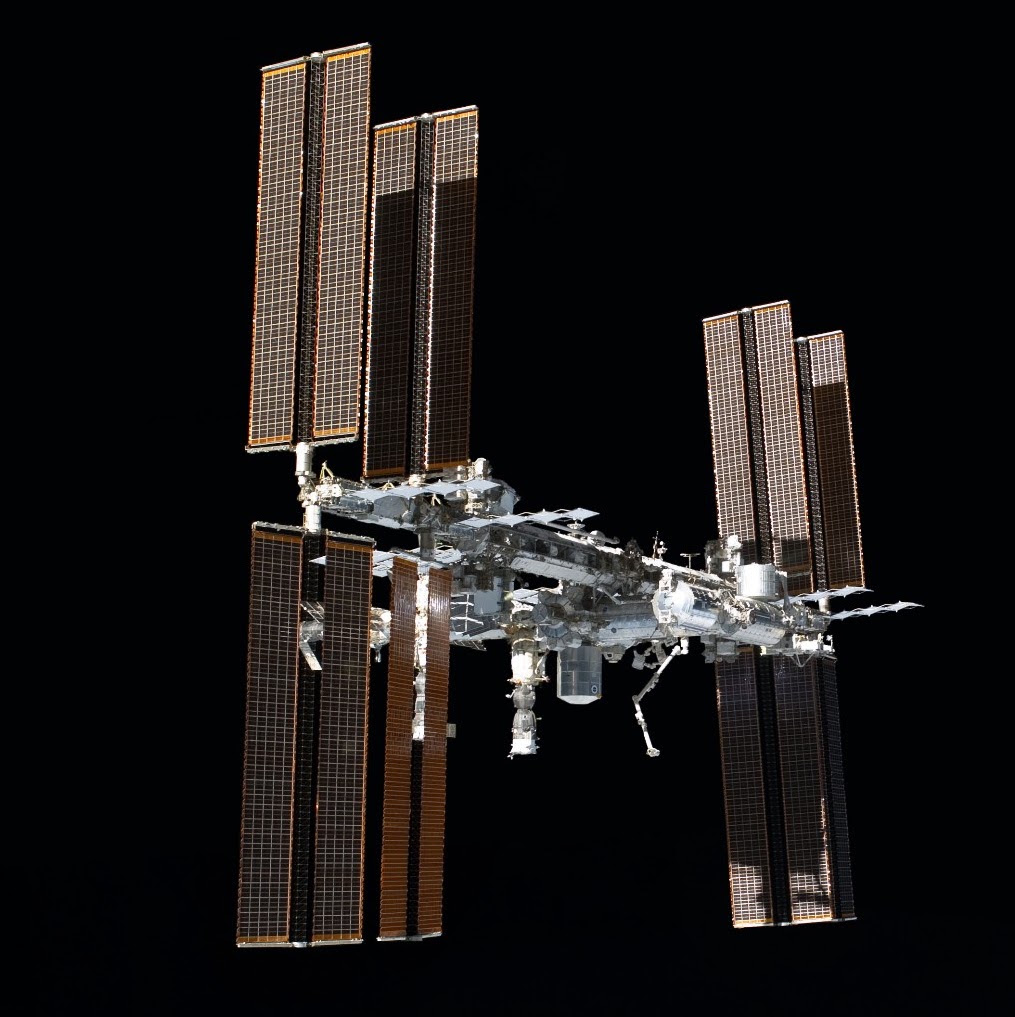
Saturday, January 30, 2016

ISS "Sunrise"

My 1/100 ISS build has officially started!

The first module, Zarya (Заря́), which means "sunrise" in Russian, has great significance as ushering in the dawn of a new era of international cooperation in space exploration.

Zarya, also known as the Functional Cargo Block (FGB), was launched on November 20, 1998 aboard a Russian Proton rocket from the Baikonur Cosmodrome Site 81 in Kazakhstan to a 400 km (250 mi) high orbit. The module was designed for a lifetime of at least 15 years. The module provided initial power and propulsion functions for the station.  Zarya's construction was funded by the United States.  The module was built at the Khrunichev State Research and Production Space Center (KhSC) in Moscow. Zarya's control system was developed by the Khartron Corp. 

Zarya is part of the free ISS Russian segment kit offered by AXM. The build consists of 5 pages of parts. The accompanying instruction manual provides fairly good assembly directions with many reference photos. An addendum to the instructions includes directions for placement of the Kurs docking navigation antennas and panels on the aft section of the module.

I started by build by first assembling the module's main body cylinder and end caps. 


Here's few important tips to point out at this stage of the build that I would like to pass along for future reference:
  1. Use a pen or pencil to help you slowly curve your part into a cylinder.  Be patient and take your time. Don't force the curving process or you will most likely end up with longitudinal creases in the surface. 
  2. This particular assembly uses a connector tab that is glued to the backside of each edge so that the edges are flush with one another when joined, avoiding a noticeable overlap on the resulting seam. Not all part joins take this approach.  However, I have found that you can cut the connector tab off and glue it to the backside in most all cases in order to always achieve a flush join, helping to minimize visible seams and improve on realism.
  3. Many curved parts have connector tab "teeth".  One important paper modeling word of advice to pass along here - "scoring". Scoring involves making an indentation on the back side of a paper bend in order to achieve a clean crease in your paper that follows the intended crease line.  Use an awl, dull needle, or backside of an exact-o knife to score the paper, making sure not to cut into the material, but rather depress/indent it. Again, take your time and use a straight edge to ensure a true score line that follows the intended tack.

I then proceeded to cut and assemble the module's fuel and oxidizer tanks.


As I mentioned earlier, Zarya was responsible during early phases of the ISS construction for propulsion functions.  Propulsion is necessary for any vehicle orbiting the Earth.  Orbits are not perfect and eventually decay due to ever-changing solar activity that affects density and fluctuations in the Earth's thermosphere, causing drag. Periodic re-boosts must occur in order to avoid orbit decay and maintain proper inclination for constant station communications and future mission optimal orbital rendezvous.  Re-boosts require fuel. Zarya has 24 large steering jets, 12 small steering jets, and two large engines that were used for re-boost and major orbital changes before the arrival of the addition of the Zvezda module.  Zarya's sixteen fuel tanks have a capacity of 5.4 metric tons of propellant. The Zarya engines are no longer used for station-keeping, however the module's fuel tanks are used to supply fuel for the Zvezda engines.

Once I decided to build the ISS, I immediately decided that I would display it by hanging it from my office ceiling.  I pondered for quite a while about how best to hang the model, knowing that the build would take a long time and would require modules to be frequently taken down to attach new modules and components.  I needed a simple mechanism that would support quick and easy detach/re-attach.  I decided to use neodymium magnets as my mounting mechanism, based on my success with using them to easily join the command and service module components in my Saturn V build.  A friend at work suggested that I peruse the offerings at K&J Magnetics.  I was quickly able to find a small ring magnet that provides a 6+ oz. pull force which would accommodate attachment to nylon filament. I'll discuss that part in more detail later in the post.

Using a liberal amount of glue, I mounted a magnet on the inside of the forward edge of the module cylinder at the module's position III (aka zenith). I then glued on the cylinder ends.  At this point I ran into my first challenge: gluing of the elongated fuel tanks to the module cylinder.  These parts have odd angles. The white glue tabs on each tank must align precisely with box outlines on the module cylinder.  The combination of odd angles on the tanks along with the curvature of the cylinder made alignment of the tabs on the box outlines a bit tricky, to say the least.     I was able to affix the tanks, but some glue was dispersed outside of the coverage areas.  Luckily, the areas were inconspicuous or covered by other parts not yet attached (pump panels).  


The aft portion of Zarya consists of two cones butted against one another.  Assembly of this section presented my second technical challenge. The cones are connected by a thin cylinder having "teeth" on both sides.  My difficulty involved precise alignment of the outer edge of each cone against the edge of the cylinder while simultaneously trying to deal with the glue applied to the teeth.  Little time was available to position the cone before the glue adherence prevented adjustment.  I was able to get the aft-side cone positioned correctly. However, I ran into problems on the fore-side cone, which resulted in a very slight crooked alignment against the cylinder edge.  I initially thought about pitching the part and starting over. However, I decided instead to produce another copy of the fore-side cone, printed on regular paper and attach it over the mis-aligned cone.  It worked and the crooked seam was covered!  I glued another magnet on the inside of the structure along the cylinder area at the zenith point and then proceeded to glue the structure to the main module cylinder.


I then affixed the aft covering.

I moved back to the module's forward section and fabricated and attached the forward steering jets propellant compressor, the conical section that connects the module main body to the forward docking unit, conical section connector panels, forward fuel tank protective shields, and protective shield targets.


I then set to work on adding the aft steering jets located on the port and starboard sides.  The build rendition of these components consists of a platform with a 2 dimensional rendition of the steering jets affixed atop to platform.


I wanted a better rendition. Drawing again from my experience with fabrication of RCS thrusters on the LEM portion of my Saturn V build, I decided to fabricate steering jets to achieve a true 3 dimensional rendition using bamboo skewers.


I moved back to the forward section of the module to fabricate the forward docking assembly.  This component consists of another cone-abutted-to-cone assembly.  The center cylinder section of this component is wider than the aft assembly, which allowed better manipulation of the cone placement and affixing process. I decided to embellish upon the printed PMA power connections, layering wire atop the printed cables to improve upon the realism effect.


I repeated the process for fabrication of the forward steering jets.  I initially made the jet nozzles a little too long and had to cut them down a bit in order to achieve the correct perspective.


Before
After (Starboard)
After (Port)
 I moved onto building of the fore and aft docking units. I started with the forward nadir passive dock, adding the ring first, then building and affixing the capture cone.  The cone is not glued, so that it can be removed in the future to allow attachment of visiting Progress and Soyuz vehicles in the interim, concluding with permanent docking of the Rassvet module.  I added another magnet at the center of this docking point to possibly use magnetic attachment of visiting vehicles.


I then built the forward Androgynous Peripheral Docking System (APDS) and aft active/hybrid docking assemblies. Both assemblies are not glued, to accommodate future connection to Pressurized Mating Adapter #1 (PMA-1) (forward), and Zvezda (aft) as these modules are added to the configuration.


I then moved back to the aft section and attached the Kurs docking navigation antennas and panels.


Moving back to the forward section, I then added the forward Kurs antenna and nadir port docking target.


The only thing left was to build the solar panels.  The kit provides two configurations; deployed and stowed. The second configuration is used later in the ISS assembly sequence.  I decided to go ahead and build both configurations.

AXM indicates printing of the solar panels on 90# card stock.  I followed the prescribed directions and attached the solar panels to the module.  However, I was disappointed in the outcome, as the panels sagged a bit at the outer ends.


I decided to construct the panels again using 110# card stock.  The result was much better, no sagging!  I proceeded to build the stowed solar panel configuration using the same card stock material.  

The build of the stowed panel assembly proved to be the most difficult part of this module's build. The scissor frame for each panel consists of four layers glued together to provide strength. Each of the frame segments required multiple cuts in order to extract the part.


Here's the result - pretty cool!


I used an orange colored pencil on the edges of the deployed and stowed solar panel in order to remove the white edge and add realism.

I was now finished with the prescribed build.  However, I wanted to add some additional touches to increase realism.  I decided to add various Kurs, Komparus, TORU, and Sirius-4 antennas to the module, based on my study of various photos and diagrams of the module. I fabricated the antennas from scratch, using 22 and 26 gauge craft wire, some tiny washers that I picked up during a recent visit to a clock and watch show with my father-in-law, and good ol' trusty bamboo skewer pieces!


All that was left was to attach magnets to nylon filament to support suspension of the module.  I first tried to glue the line directly into the hole of the ring.  The line easily pulled out.  Next, I tried to make a stopper using conical sections of bamboo.  I was unable to successfully wedge the line into the magnet hole using the bamboo. Next, I tried to fabricate a wedge using aluminium foil wrapped around a knotted end of line, dabbed with a bit of glue. The foil was pliable enough to allow formation of a wedge into the hole of the magnet...and it held and provided a flush fit.  I attached both magnets and affixed the line to the module.  Voila!


Zarya is now complete and currently on display at my office.  My wife let me borrow one of her Christmas ornament display stands so that I can display the module on my desk for co-workers to closely inspect before I re-locate it to a ceiling mount. 

I'm ready to move onto the next module, Unity!

Sunday, January 3, 2016

I'm Sorry Dave...

I am a big fan of 2001: A Space Odyssey. The film was groundbreaking in its accurate depiction of the cold vacuum and loneliness of space. The film's special effects set the bar for realism expected by viewers in sci-fi films that followed it.

During my search efforts to embellish my Saturn V build, I ran across a fabulous rendition of the HAL 9000 interface that looked quite realistic and was simple to build.  I decided to build the model and adorn the back of one of my monitors at work to help keep an "eye" on things.  I love the realistic 3-D look!

Friday, January 1, 2016

My Christmas Papercraft Project

This particular story isn't about a model build, but it deals with crafting something cool from paper, so I thought that you may be interested in reading about this little adventure.

A couple of months ago one of my cousins posted a couple of photos to Facebook that intrigued me. The photos were of a postcard that my paternal grandfather sent to his mother in late May of 1919, announcing his return from World War I.

I am a bit of a history buff, particularly in history dealing with World War I and II.  I was aware that my grandfather was in the "Great War", but I didn't know any particulars about what he did or where he was deployed.

The postcard provided the key that I needed help me find out more about my grandfather's role in the war. The card contained information written down by my grandfather about the unit that he was a member of, the 305th Field Signal Battalion.  Using this piece of information, I was able to perform some searches and stumbled across a number of sources relating my grandfather's unit to the 80th Division.

Wikipedia provided a great overview of the 80th Division's history.  The 80thdivision.com site provided more historical information, along with information about the 80th Division Veterans Association, reunions and various points of contact. The Troubleshooters site provided a boot camp photo of my grandfather's battalion, along with information about an excellent book about the history of the 80th Division in WWI.

I decided to craft a Christmas gift for my dad using my newly acquired information. I searched a bit more and was easily able to find a copy of my grandfather's draft registration card on  familysearch.org.

I assembled the artifacts into a collage that I mounted onto a 16x20 framed layout and also gave my dad a copy of the book that I discovered. The result was great and my dad loved it!  I'm looking forward to continue my research into the 80th Division using the book and hopefully attending a future 80th Division Veterans Association meeting.  I also hope to find additional photos containing my grandfather.

Wednesday, December 16, 2015

My next project - the ISS!!


O.K., as promised in my first post, I'm starting my new undertaking - a 1/100 scale paper-only build of the International Space Station!

I'll be using excellent plans created by Alfonso Moreno. I will be building the model following the order that the station was assembled in space and I am going to suspend the model from the ceiling of my office.

I will be blogging about each component as I build it.  I've also created a progress display on the outer window of my office to provide an overview of my project, highlight the current segment under construction, and convey overall progress in the assembly sequence, using a nice, informative timeline from the NASA site.

Here's a picture of the progress display at my office.


I'm excited about this endeavour and I hope that you follow along. Stay tuned!

Monogram Heritage Series Saturn V 1/144 Scale Build


As I mentioned in my first blog post, my recent build of the 1/144 scale Monogram Heritage Series Apollo Saturn V is responsible for kindling my interest in paper modeling. This article will hopefully give you some introspect in the process that I followed to build this kit, show you how I integrated the use of paper components in order to enhance the overall model detail, and hopefully teach you a few things about the Saturn V that you didn't know.

I seriously started on this model build in late October, 2014.  At that time three of the four of my children were away at college and my youngest son's high school soccer season had just ended, so, I had a little spare time on my hands to "tinker" with something.

Here's a bit history about this model, the amazing vehicle it represents, and events in my life that help to tell its story. The model itself has been in my possession since the summer of 1992, having been given to my by a co-worker and fellow model enthusiast, Buzz, upon his departure from my company for a new job in San Antonio.  Buzz and I would often visit the local hobby store at lunch to browse the models and Buzz must have noticed my interest in this particular model during one of our visits.

My wife and I purchased our first house that same summer, and Buzz's gift was shelved so that I could focus on a newly-acquired "honey do" list of household tasks. I tinkered with the kit a little on-off over the next 8 years, with activity limited to separating and dry fitting some of the cylindrical and other large parts along with removing excess plastic from various areas of the F1 and J2 engine bell parts using a needle file. During that time, we had four kids and moved to a larger house to accommodate our growing family.  The model was "allowed" to make the move to the new abode and ended up residing on the floor of our kitchen pantry closet, where it sat untouched until last October.

During the early to mid 1990's my company was involved with development of flight and mission planning software applications for the space station and I frequently visited the Houston area for meetings. I would often visit the Johnson Space Center and the famous Outpost astronaut bar and hang-out during my trips.  I also was able to see mission control, early station mock-ups, moon rock collections, the neutral buoyancy lab, and, of course a display of the Saturn V that at the time was located outdoors at the space center.  The display has since been enclosed within walled facility to harbor it from the elements after a two year restoration project concluding in 2007.

If you've never seen the Saturn V in person, then I highly recommend that you swing by and take a look at one the next time that you're near Cape Canaveral, FL, Huntsville, AL, or Clear Lake, TX.  The vehicle is a true engineering marvel, rising over 360 feet and weighing more than 6.5 million pounds when it was fully stacked and loaded with fuel and the Apollo payload on the launch pad.  The vehicle could place up to 260,000 pounds of payload into low Earth orbit. To date, the Saturn V remains as the only launch vehicle that has been built to take humans beyond low Earth orbit.

O.K., so enough background.  Let's talk about the build.

I started my work with the F1 engines located on the aft section of stage 1 (a.k.a., S-IC) .  These components consisted of 2-part halves for each engine.  The casts for these parts were clean and provided good detail on the exterior nozzle extension, turbine exhaust manifold and heat exchanger components.  A bit of excess plastic mold was present between the heat exchanger and the thrust chamber.  This was probably done intentionally by Monogram in order to reinforce the part to avoid having the heat exchanger break off accidentally.  I chose to remove this excess plastic in order to increase detail and realism.  Most of the removal work was performed in the 1990's period.  I completed the removal and smoothed over the cutout areas as part of the re-start effort.

The resulting F1 parts looked great when dry fitted.  However, I was disappointed by lack of detail provided by the kit in the upper bell and interior nozzle areas, so I started looking for ideas about how to enhance these components to add detail.  At first, I attempted to fabricate various missing valve assemblies using bent solid gauge insulated wire.  Test fits of the assemblies looked OK, but still weren't detailed enough for my liking. Repeated searches related to F1 engine models let me to a page on the Lower Hudson Valley Paper Model E-Gift Shop site of a spectacular 1/48 model of the F1 engine created by Greelt Peterusma, along with some enhancement modifications to the model provided by Jasper (last name unknown). I decided to use parts from both of these kits to enhance my engines, adjusting the scale to 1/144, which resulted in the following outcome.


Next, following the traditional plastic modeling approach, I assembled all of the stage "tube" components and applied 2-3 even coats of Testors flat white (aerosol application) to all parts.  I am always amazed at how much better and realistic a model looks when it's painted, even at this stage in the process.

The Monogram rendition of the aft portion of stage 2 (a.k. a, S-II) is downright sad.  The engine array and heat shield remind me of a tupperware serving tray! I don't understand how this one portion of the model could be so off-base in following the overall Saturn V design on comparison to the rest of the model.


I knew that I had to replace this part of the model, or the overall level of realism that I wanted to convey for this build would not be met. Greelt saved the day again, providing an amazing build for the J2 engines for this stage that happened to also be listed on the Lower Hudson Valley site. Scaling the plans down to 1/144, I was able to build 5 of these engines. Meticulous effort, often using a magnifying glass, was required to assemble the smaller parts on these engines. I used craft beads for the helium starter tanks. I was elated with the result and knew that I was on the right track to build a model with the detail that I desired.


Removal of the stock Monogram design also required me to fabricate a S-II thrust structure for this section.   I went searching again for ideas and stumbled upon a paper model of S-II developed by Frederic Bouchar that provided realistic thrust structure design which I could use in my refit.  I ended up replacing the model's cruciform engine mount with a from-scratch version that I made using balsa to provide better strength and a more realistic look.  I studied some awesome photos from Mark Rasmussen's Saturn V styrene scratch-build site to add additional detail to the stage using paper, balsa, fine wire, and bamboo, which resulted in a rendition of the S-II aft section that I'm very pleased with!


The forward portion of the stock S-II model had characteristics that I also observed during my examination of Saturn V photos from Kennedy Space Cener (KSC)  and wanted to eliminate.  The forward section of the model is equipped with what I found in my research to be the ground support equipment (GSE). According to information that I found at heroicrelics.org, the S-II forward section GSE provided in the Monogram kit is comprised of the stage erecting sling, forward hoisting frame, and forward support ring, which allowed the S-II to be moved from a horizontal transport orientation to a vertical stacking position upon arrival at KSC.  The GSE was removed from the forward area of the S-II after it was stacked, exposing the forward bulkhead that covers the LOX tank. The stock part was accurate in the real world Saturn V for the purpose of S-II transport and stacking, however I wanted to depict my Saturn V build in a flight configuration.   I needed to fabricate the forward bulkhead, as removal of the GSE would expose a void in the top area of the S-II.

The Lower Hudson Valley site came to the rescue again, providing me with a link to a paper rendition of the S-II bulkhead as part of a complete 1/48 scale paper version of the Saturn V. This particular model is an 8 foot giant, comprised of sections created by Greelt and others, and assembled into a single set of plans by Jean-Paul (last name unknown). I'm saving this one for a future paper-only Saturn V build. Here's a photo of the S-II forward bulkhead that I built, using a scaled down version of the Jean-Paul plans.


By this point in the build I was more confident than ever in my accomplishments with adding detail, which encouraged me to continue adding detail wherever I could.  I moved on to stage 3 (a.k.a S-IV). This part of the model is fairly detailed as-is and, unlike the S-II engines, the J2 engine provided for this stage was quite detailed, so I decided to use it. I saw opportunity to enhance the aft section of this stage to match details that I studied from various photos taken of the KSC, Marshall Space Center (MSFC), and Johnson Space Center (JSC) Saturn V displays. I embellished the stock engine with a helium starter tank as I had done on the S-II engines that I fabricated. I also added helium pressure spheres on the thrust structure using glass beads.  I also included control cabling and harnesses, the LH2 feed line to the J2 engine, the O2/H2 burner, and repressurization tubing.  I referred to excellent documentation regarding the makeup of the S-IV repressurization system on heriocrelics.org,  This site was invaluable in assisting me in my detailing efforts and it also educated me in the amazing engineering behind this stage. The S-IV was designed for engine re-start capability that was necessary for the crucial trans-lunar injection (TLI) burn that sent the astronauts and their Apollo payload toward the moon.  


Moving on up the Saturn V stack, I next tackled work on the lunar excursion module (LEM).  The Monogram instructions for detailing the LEM were minimal, consisting of a few simple decals to vaguely identify a silhouette for the the iconic, quirky-looking ascent stage, along with similar decals to provide outline for the boxy decent stage, The example shown on the packaging was pathetic, and I knew, even with the small scale that I was dealing with, that I could add detail to make this component look much more realistic. 

I had just come back from a business trip in mid-January before tackling this part of the build.  During my trip, a co-worker, Bill, showed me some photos of a 1/48 scale paper build of the Apollo 13 LEM, Aquarious, that he had seen on one of his daily news feeds.   I was able to track down the source of the model to an outstanding Japanese modeler known as uhu02 and I was astounded as to the intricacy and detail that was created using just paper! This is the best paper model that I've run across so far, hands down! The model, like all others on uhu02's site, is fully detailed, inclusive of features under the outer LEM skin, depicting various tanks, components, structural skeleton and the interior crew area, wow!

Suddenly, I had an idea as I gazed at uhu02's masterpiece. Why not try and use the exterior panels from uhu02's design to cover my LEM components?  Great idea!  I proceeded to scale applicable pages from the uhu02 design down in order to fit my LEM.  Amazingly, I was able to find the right reduction percentage that fit after only a couple of tries.  I ended up printing the parts on regular paper instead of card stock so that I could obtain a skin-tight fit.  I applied a thin film of glue and carefully affixed the paper to the plastic, taking special care to follow the various contours on the LEM ascent stage.  The result effect was very decoupage-like.  I could not tell that the paper had been applied, rather it looked like the form had been directly painted on by hand! 


Encouraged by the result, I decided to forge ahead and follow the same technique on the descent stage using the same scaling factor. Again, I ended up with amazing results and gained detail provided by uhu02's implementation of the scientific experiments cargo bay, s-band antenna. RCS deflectors, and egress platform.  I augmented the micrometeorite foil blanket coverage on the top and bottom areas of the descent stage and landing legs with gold foil from a Rollo candy wrapper and thin aluminum foil. I added the steerable s-band antenna and VHF antennas using the uhu02 plans.  The result was awesome!


I then moved my work efforts to the command and service module.  The Monogram instructions prescribed painting the command module  and targeted areas of the service module with silver paint as the sole detail instruction. I wanted to implement much more with this portion of the model and I also wanted to allow the components to be displayed in either a connected or separated orientation.

I glued magnets to the inside of the command module heat shield and inside of the top portion of the service module to allow both parts to be easily connected or disconnected by magnetic force.

After reviewing dozens of photos and diagrams, I covered the command module with a thin layer of aluminum foil to attain the "shiny" aluminum appearance familiar in many photos.  I roughed up the heat shield using fine sandpaper and painted the heat shield using a copper-colored sharpie to produce a dull copper-colored look. I  fabricated a docking adapter and affixed it to the top of the command module and blacked in the port holes to help visually distinguish them. I scaled down service module plans from the 1/48 scale  Lower Hudson Valley site's Saturn V model and affixed radiator panels, scimitar antennas, the command module flyaway umbilical, and high-gain s-band antenna. Again, great detail results!


I chose not to apply any paint to the boost protective cover (BPC) or launch escape tower assembly. All of the photos that I previewed of these components depict them as having a glossy finish, so I decided to leave the bare white plastic here to achieve the desired effect.  I drilled a small circular hole at the center hatch port hole position on the BPC to match actual design, and I notched the opposite side of the BCP to accommodate presence of the flyaway umbilical connection between the command and service modules.

At this point, I moved back to the S-1C thrust structure, adding air scoops to the inside edges of the four outboard engine fairings and support stringers.  I affixed the F1 engines to the thrust structure base to complete the assembly in this area.


All that was left was to apply the iconic roll pattern, sway targets, first motion targets, and insignia decals.  I was nervous about applying the roll pattern, as any slight error in applying the black pattern would be starkly apparent against the white base.  The roll patterns cover areas on the model that have vertical corrugation patterns which further complicates a clean application, especially if using paint.

I decided to apply the roll patterns using a black sharpie.  Using a pen as opposed to brush or aerosol paint application gave me a much finer level of control.  I used painter's masking tape where possible to mark vertical and horizontal lines of demarcation and keep my patterns clean, and straight.  I made a few mistakes, but I found that, unlike paint, I could easily scrape the sharpie color off to correct my errors, as long as it was done soon after the mistake was made.

Sway targets located on the S-IV reduction cone were applied following awesome marking diagrams that I found on apollosaturn.com.  I also referenced this web site to verify placement of kit-provided decals and first motion targets on the S-IC and S-II stages.

My final task was to build a base for horizontal display of all stages, akin to the orientation of the actual Saturn V displays at KFC, MSFC, and JSC.  My father-in-law provided me with a beautiful 3.5' X 6" plank of ponderosa pine with a nice semi-gloss polyurethane finish for mounting the model. I wanted to elevate each stage on the base, allowing for space between each stage to provide visual access to inter-stage details.  I also wanted to preserve the relative stage heights and alignments, while also preserving the narrowing taper of the model as you progress up the stack. I ended up using formed sections of a rubber-coated wire to build platform stands for the S-IC, S-II, and S-IV stages.  The flexible wire allowed me to tweak each stand in order to achieve optimal shape and position for each stage so that I could achieve the orientation that I desired.  Here's some views of the finished product. I am so proud of it and I hope that you've enjoyed the story of how I created it!