
The first module, Zarya (Заря́), which means "sunrise" in Russian, has great significance as ushering in the dawn of a new era of international cooperation in space exploration.
Zarya, also known as the Functional Cargo Block (FGB), was launched on November 20, 1998 aboard a Russian Proton rocket from the Baikonur Cosmodrome Site 81 in Kazakhstan to a 400 km (250 mi) high orbit. The module was designed for a lifetime of at least 15 years. The module provided initial power and propulsion functions for the station. Zarya's construction was funded by the United States. The module was built at the Khrunichev State Research and Production Space Center (KhSC) in Moscow. Zarya's control system was developed by the Khartron Corp.
Zarya is part of the free ISS Russian segment kit offered by AXM. The build consists of 5 pages of parts. The accompanying instruction manual provides fairly good assembly directions with many reference photos. An addendum to the instructions includes directions for placement of the Kurs docking navigation antennas and panels on the aft section of the module.
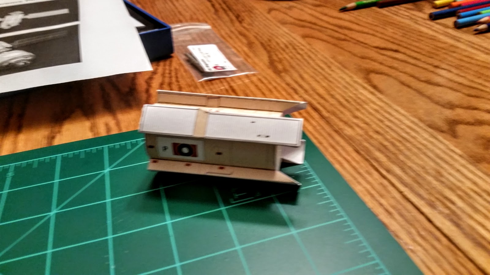
I started by build by first assembling the module's main body cylinder and end caps.

Here's few important tips to point out at this stage of the build that I would like to pass along for future reference:
- Use a pen or pencil to help you slowly curve your part into a cylinder. Be patient and take your time. Don't force the curving process or you will most likely end up with longitudinal creases in the surface.
- This particular assembly uses a connector tab that is glued to the backside of each edge so that the edges are flush with one another when joined, avoiding a noticeable overlap on the resulting seam. Not all part joins take this approach. However, I have found that you can cut the connector tab off and glue it to the backside in most all cases in order to always achieve a flush join, helping to minimize visible seams and improve on realism.
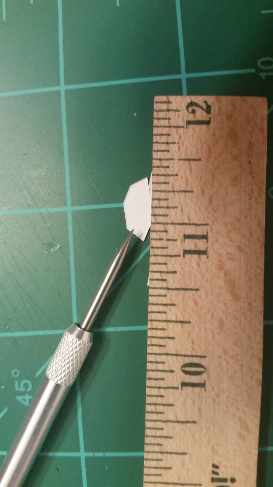
- Many curved parts have connector tab "teeth". One important paper modeling word of advice to pass along here - "scoring". Scoring involves making an indentation on the back side of a paper bend in order to achieve a clean crease in your paper that follows the intended crease line. Use an awl, dull needle, or backside of an exact-o knife to score the paper, making sure not to cut into the material, but rather depress/indent it. Again, take your time and use a straight edge to ensure a true score line that follows the intended tack.

I then proceeded to cut and assemble the module's fuel and oxidizer tanks.

As I mentioned earlier, Zarya was responsible during early phases of the ISS construction for propulsion functions. Propulsion is necessary for any vehicle orbiting the Earth. Orbits are not perfect and eventually decay due to ever-changing solar activity that affects density and fluctuations in the Earth's thermosphere, causing drag. Periodic re-boosts must occur in order to avoid orbit decay and maintain proper inclination for constant station communications and future mission optimal orbital rendezvous. Re-boosts require fuel. Zarya has 24 large steering jets, 12 small steering jets, and two large engines that were used for re-boost and major orbital changes before the arrival of the addition of the Zvezda module. Zarya's sixteen fuel tanks have a capacity of 5.4 metric tons of propellant. The Zarya engines are no longer used for station-keeping, however the module's fuel tanks are used to supply fuel for the Zvezda engines.
Once I decided to build the ISS, I immediately decided that I would display it by hanging it from my office ceiling. I pondered for quite a while about how best to hang the model, knowing that the build would take a long time and would require modules to be frequently taken down to attach new modules and components. I needed a simple mechanism that would support quick and easy detach/re-attach. I decided to use neodymium magnets as my mounting mechanism, based on my success with using them to easily join the command and service module components in my Saturn V build. A friend at work suggested that I peruse the offerings at K&J Magnetics. I was quickly able to find a small ring magnet that provides a 6+ oz. pull force which would accommodate attachment to nylon filament. I'll discuss that part in more detail later in the post.
Using a liberal amount of glue, I mounted a magnet on the inside of the forward edge of the module cylinder at the module's position III (aka zenith). I then glued on the cylinder ends. At this point I ran into my first challenge: gluing of the elongated fuel tanks to the module cylinder. These parts have odd angles. The white glue tabs on each tank must align precisely with box outlines on the module cylinder. The combination of odd angles on the tanks along with the curvature of the cylinder made alignment of the tabs on the box outlines a bit tricky, to say the least. I was able to affix the tanks, but some glue was dispersed outside of the coverage areas. Luckily, the areas were inconspicuous or covered by other parts not yet attached (pump panels).

The aft portion of Zarya consists of two cones butted against one another. Assembly of this section presented my second technical challenge. The cones are connected by a thin cylinder having "teeth" on both sides. My difficulty involved precise alignment of the outer edge of each cone against the edge of the cylinder while simultaneously trying to deal with the glue applied to the teeth. Little time was available to position the cone before the glue adherence prevented adjustment. I was able to get the aft-side cone positioned correctly. However, I ran into problems on the fore-side cone, which resulted in a very slight crooked alignment against the cylinder edge. I initially thought about pitching the part and starting over. However, I decided instead to produce another copy of the fore-side cone, printed on regular paper and attach it over the mis-aligned cone. It worked and the crooked seam was covered! I glued another magnet on the inside of the structure along the cylinder area at the zenith point and then proceeded to glue the structure to the main module cylinder.

I then affixed the aft covering.
I moved back to the module's forward section and fabricated and attached the forward steering jets propellant compressor, the conical section that connects the module main body to the forward docking unit, conical section connector panels, forward fuel tank protective shields, and protective shield targets.


I then set to work on adding the aft steering jets located on the port and starboard sides. The build rendition of these components consists of a platform with a 2 dimensional rendition of the steering jets affixed atop to platform.

I wanted a better rendition. Drawing again from my experience with fabrication of RCS thrusters on the LEM portion of my Saturn V build, I decided to fabricate steering jets to achieve a true 3 dimensional rendition using bamboo skewers.


I repeated the process for fabrication of the forward steering jets. I initially made the jet nozzles a little too long and had to cut them down a bit in order to achieve the correct perspective.
I moved onto building of the fore and aft docking units. I started with the forward nadir passive dock, adding the ring first, then building and affixing the capture cone. The cone is not glued, so that it can be removed in the future to allow attachment of visiting Progress and Soyuz vehicles in the interim, concluding with permanent docking of the Rassvet module. I added another magnet at the center of this docking point to possibly use magnetic attachment of visiting vehicles.
I then built the forward Androgynous Peripheral Docking System (APDS) and aft active/hybrid docking assemblies. Both assemblies are not glued, to accommodate future connection to Pressurized Mating Adapter #1 (PMA-1) (forward), and Zvezda (aft) as these modules are added to the configuration.


Using a liberal amount of glue, I mounted a magnet on the inside of the forward edge of the module cylinder at the module's position III (aka zenith). I then glued on the cylinder ends. At this point I ran into my first challenge: gluing of the elongated fuel tanks to the module cylinder. These parts have odd angles. The white glue tabs on each tank must align precisely with box outlines on the module cylinder. The combination of odd angles on the tanks along with the curvature of the cylinder made alignment of the tabs on the box outlines a bit tricky, to say the least. I was able to affix the tanks, but some glue was dispersed outside of the coverage areas. Luckily, the areas were inconspicuous or covered by other parts not yet attached (pump panels).
The aft portion of Zarya consists of two cones butted against one another. Assembly of this section presented my second technical challenge. The cones are connected by a thin cylinder having "teeth" on both sides. My difficulty involved precise alignment of the outer edge of each cone against the edge of the cylinder while simultaneously trying to deal with the glue applied to the teeth. Little time was available to position the cone before the glue adherence prevented adjustment. I was able to get the aft-side cone positioned correctly. However, I ran into problems on the fore-side cone, which resulted in a very slight crooked alignment against the cylinder edge. I initially thought about pitching the part and starting over. However, I decided instead to produce another copy of the fore-side cone, printed on regular paper and attach it over the mis-aligned cone. It worked and the crooked seam was covered! I glued another magnet on the inside of the structure along the cylinder area at the zenith point and then proceeded to glue the structure to the main module cylinder.
I then affixed the aft covering.
I moved back to the module's forward section and fabricated and attached the forward steering jets propellant compressor, the conical section that connects the module main body to the forward docking unit, conical section connector panels, forward fuel tank protective shields, and protective shield targets.


I then set to work on adding the aft steering jets located on the port and starboard sides. The build rendition of these components consists of a platform with a 2 dimensional rendition of the steering jets affixed atop to platform.

I wanted a better rendition. Drawing again from my experience with fabrication of RCS thrusters on the LEM portion of my Saturn V build, I decided to fabricate steering jets to achieve a true 3 dimensional rendition using bamboo skewers.


I moved back to the forward section of the module to fabricate the forward docking assembly. This component consists of another cone-abutted-to-cone assembly. The center cylinder section of this component is wider than the aft assembly, which allowed better manipulation of the cone placement and affixing process. I decided to embellish upon the printed PMA power connections, layering wire atop the printed cables to improve upon the realism effect.


I repeated the process for fabrication of the forward steering jets. I initially made the jet nozzles a little too long and had to cut them down a bit in order to achieve the correct perspective.
 |
| Before |
 |
| After (Starboard) |
 |
| After (Port) |


I then built the forward Androgynous Peripheral Docking System (APDS) and aft active/hybrid docking assemblies. Both assemblies are not glued, to accommodate future connection to Pressurized Mating Adapter #1 (PMA-1) (forward), and Zvezda (aft) as these modules are added to the configuration.


I then moved back to the aft section and attached the Kurs docking navigation antennas and panels.


Moving back to the forward section, I then added the forward Kurs antenna and nadir port docking target.

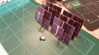
The only thing left was to build the solar panels. The kit provides two configurations; deployed and stowed. The second configuration is used later in the ISS assembly sequence. I decided to go ahead and build both configurations.
AXM indicates printing of the solar panels on 90# card stock. I followed the prescribed directions and attached the solar panels to the module. However, I was disappointed in the outcome, as the panels sagged a bit at the outer ends.

I decided to construct the panels again using 110# card stock. The result was much better, no sagging! I proceeded to build the stowed solar panel configuration using the same card stock material.
The build of the stowed panel assembly proved to be the most difficult part of this module's build. The scissor frame for each panel consists of four layers glued together to provide strength. Each of the frame segments required multiple cuts in order to extract the part.

Here's the result - pretty cool!


I used an orange colored pencil on the edges of the deployed and stowed solar panel in order to remove the white edge and add realism.
I was now finished with the prescribed build. However, I wanted to add some additional touches to increase realism. I decided to add various Kurs, Komparus, TORU, and Sirius-4 antennas to the module, based on my study of various photos and diagrams of the module. I fabricated the antennas from scratch, using 22 and 26 gauge craft wire, some tiny washers that I picked up during a recent visit to a clock and watch show with my father-in-law, and good ol' trusty bamboo skewer pieces!

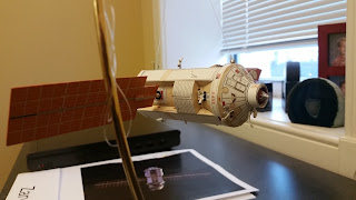
All that was left was to attach magnets to nylon filament to support suspension of the module. I first tried to glue the line directly into the hole of the ring. The line easily pulled out. Next, I tried to make a stopper using conical sections of bamboo. I was unable to successfully wedge the line into the magnet hole using the bamboo. Next, I tried to fabricate a wedge using aluminium foil wrapped around a knotted end of line, dabbed with a bit of glue. The foil was pliable enough to allow formation of a wedge into the hole of the magnet...and it held and provided a flush fit. I attached both magnets and affixed the line to the module. Voila!


Zarya is now complete and currently on display at my office. My wife let me borrow one of her Christmas ornament display stands so that I can display the module on my desk for co-workers to closely inspect before I re-locate it to a ceiling mount.
I'm ready to move onto the next module, Unity!


